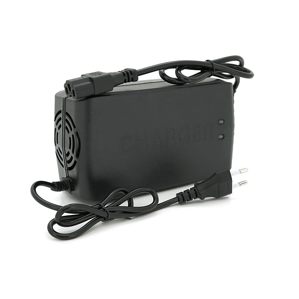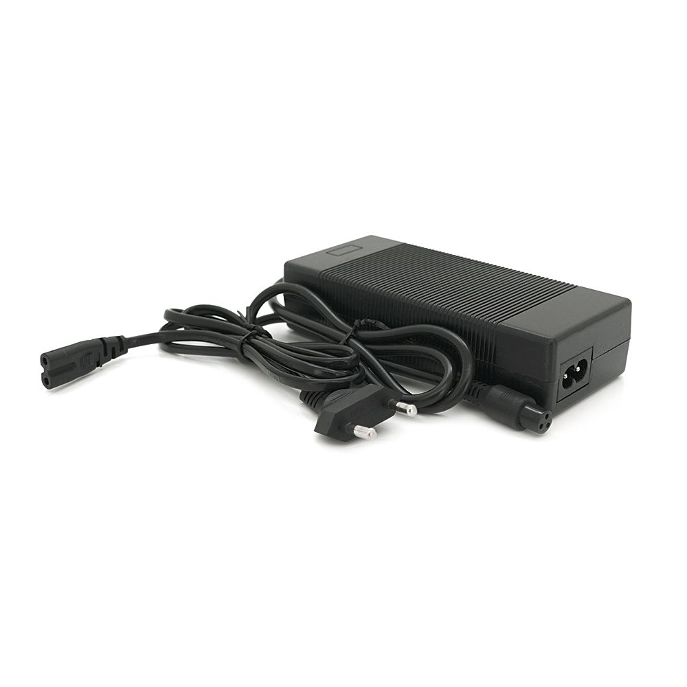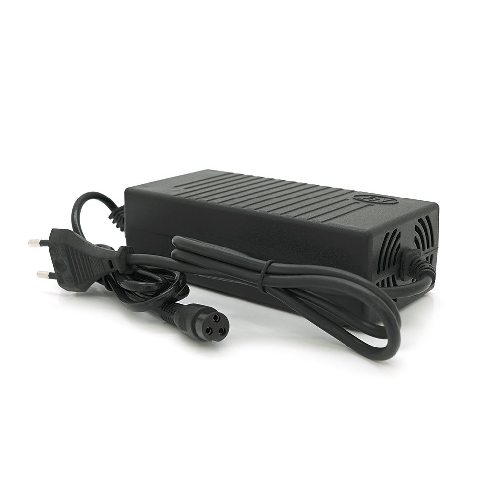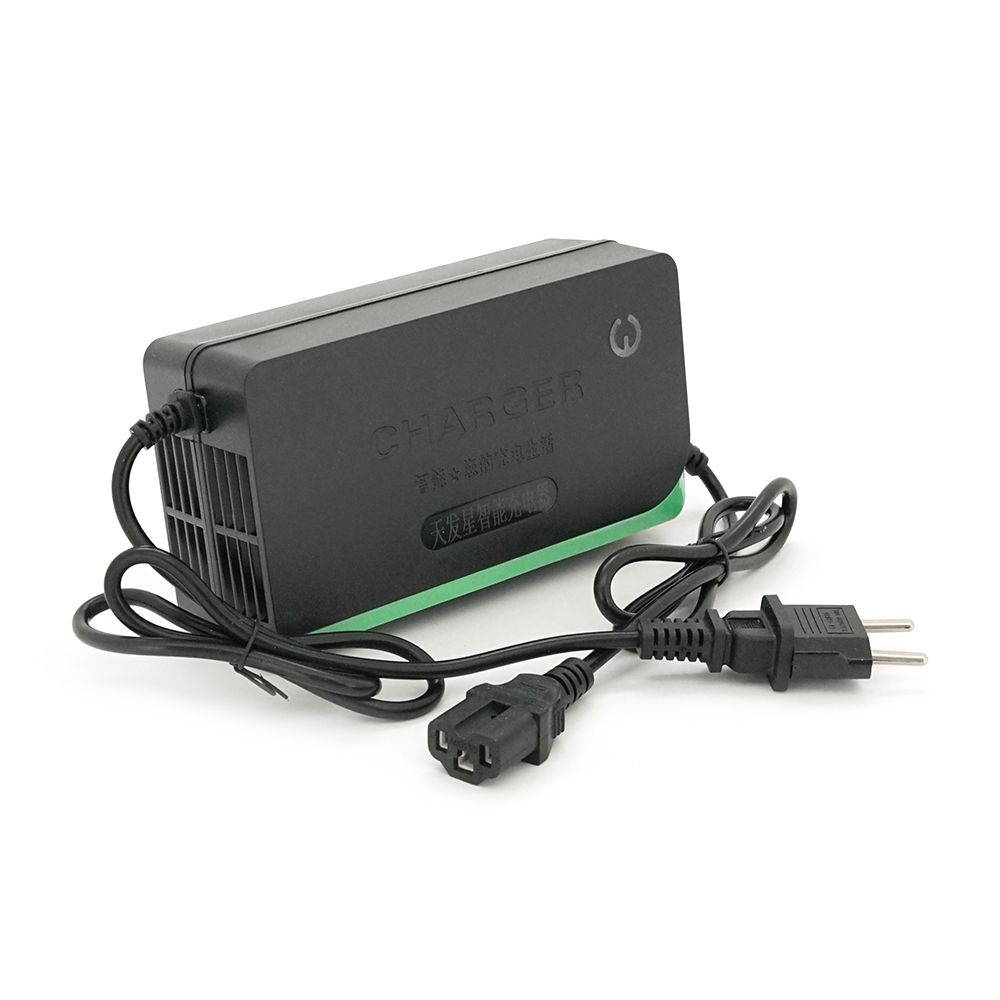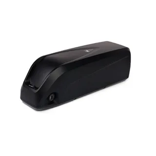
48V/G70 Battery Enclosure for Electric Vehicles
Voltronic
2,808 ₴
SKU 23738
A control unit for an electric vehicle brushless motor is an essential link in the electrical component system.
Without a controller, the electric motor cannot even start, let alone operate fully. The battery pack has 2 poles
– positive and negative, and the hub motor has 3 phase wires. Therefore, it is impossible to connect the battery and motor directly.
An additional link is used for this – the control unit.
Functions performed:
It is the controller that forms a rotating magnetic field in the stator winding of the hub motor and receives corresponding signals about the rotor position.
Signals come from Hall sensors, and when controlling sensorless motors, the rotor position is determined by back-EMF.
In addition, the controller manages the electric motor:
- allows changing the movement speed – by changing the position of the throttle grip, the number of voltage pulses supplied per second to the
windings changes, and wheel rotation accelerates or slows down;
- Provides energy regeneration during motor braking.
The controller acts as a step-down converter, so the phase current passing through the motor windings can be much
higher than the battery current coming from the battery pack to the controller. It is this current that determines the power supplied to the motor.
For example, when using a hub motor with a rated power of 1000 W, values up to 2000-2500 W can be quickly obtained.
The main thing is to use a suitable controller and constantly monitor the temperature to prevent motor overheating.
Circuit of the controller for an electric bicycle or electric scooter:
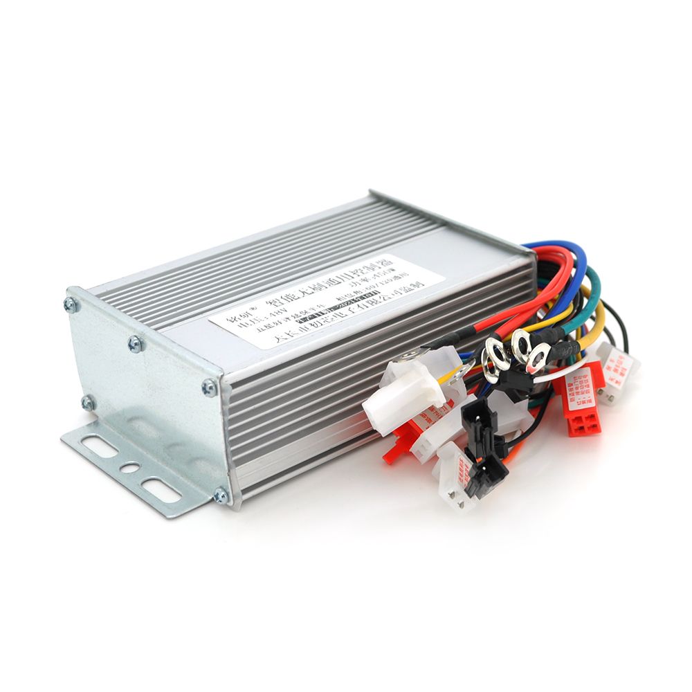
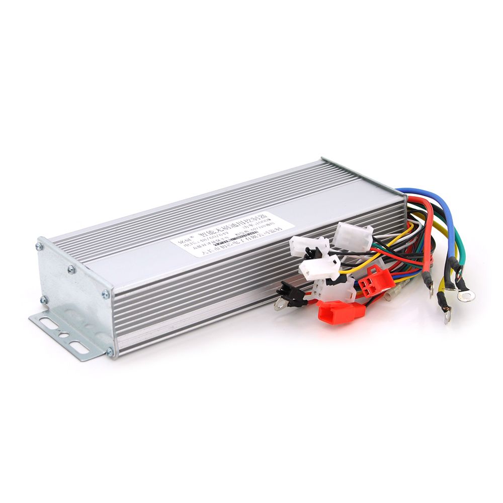
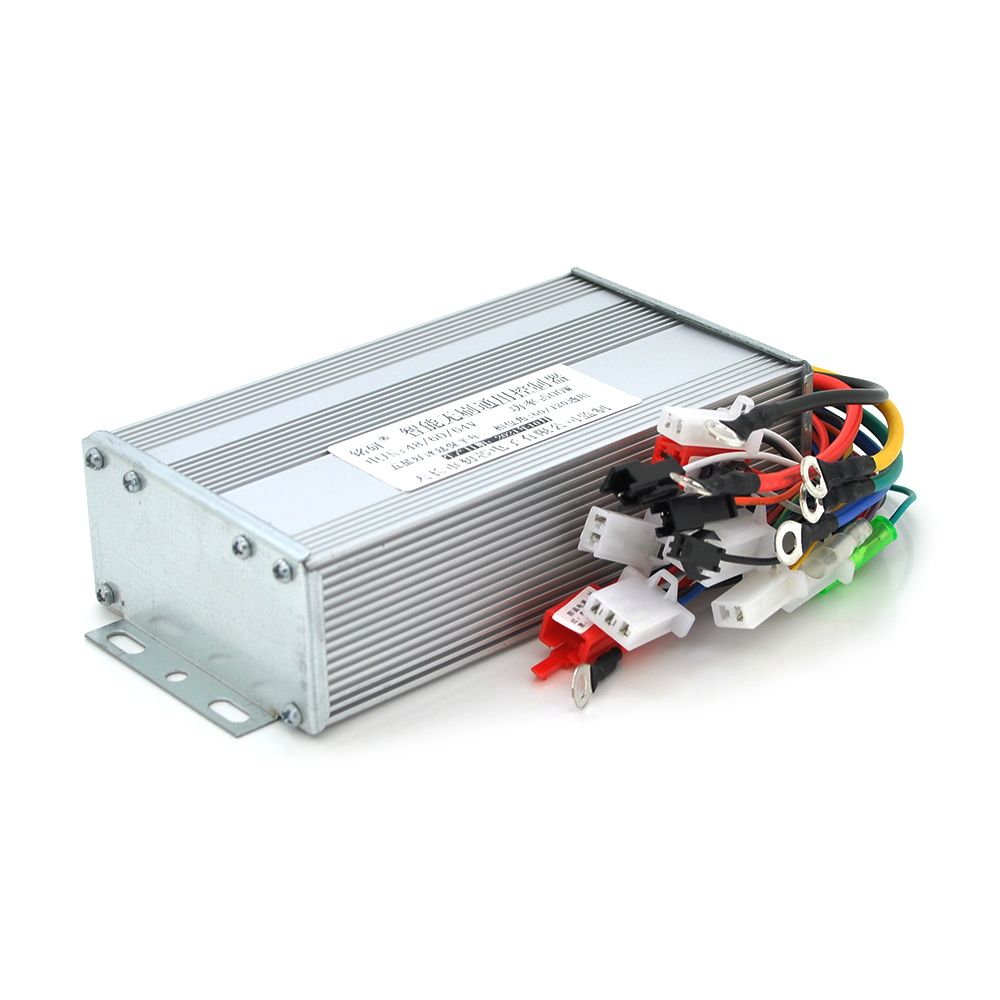
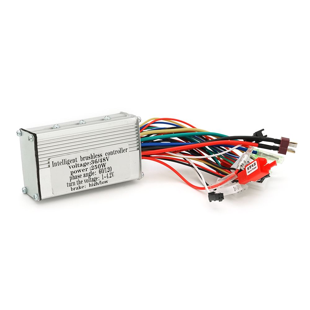
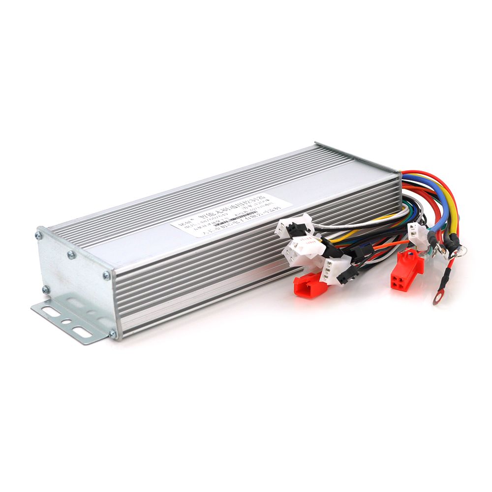
The controller for an electric bicycle or scooter has an aluminum casing from which multicolored wires with connectors emerge
for connecting various devices.
Hidden inside are:
• main node – microcontroller;
• power components – current shunt resistors, capacitors, transistors;
• 12 V and 5 V step-down converters – providing power to the microcontroller and peripheral devices (position sensors, throttle lever).
Connection diagram
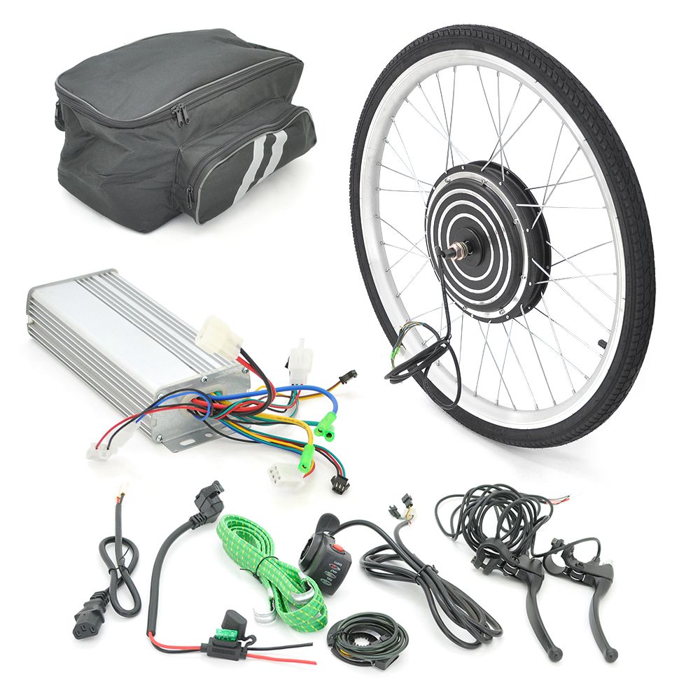
The controller for an electric scooter, e-bike, or electric kick scooter is connected according to the diagram supplied with it.
The main thing is not to rush and carefully understand the assignment of the wires.
The general connection principle looks like this:
• Thick black and red wires – connected to the battery pack observing polarity. At this time, a "spark" may appear and even some scorching of the connectors is possible. This is normal – this is how the input capacitors of the controller charge. To eliminate sparking, it is enough to briefly connect the controller and battery pack via a resistor with a resistance of dozens of ohms or use a light bulb. When the capacitors are charged, the controller can be safely connected to the battery pack without intermediaries.
• A triplet of thick wires of different colors – provides connection to the phase wires of a 3-phase electric motor.
• A bundle of 5 thin multicolored wires – goes to the hub motor wiring providing power and signal transmission from position sensors.
• A separate red wire – ignition. When closed to the battery pack positive terminal, the controller turns on.
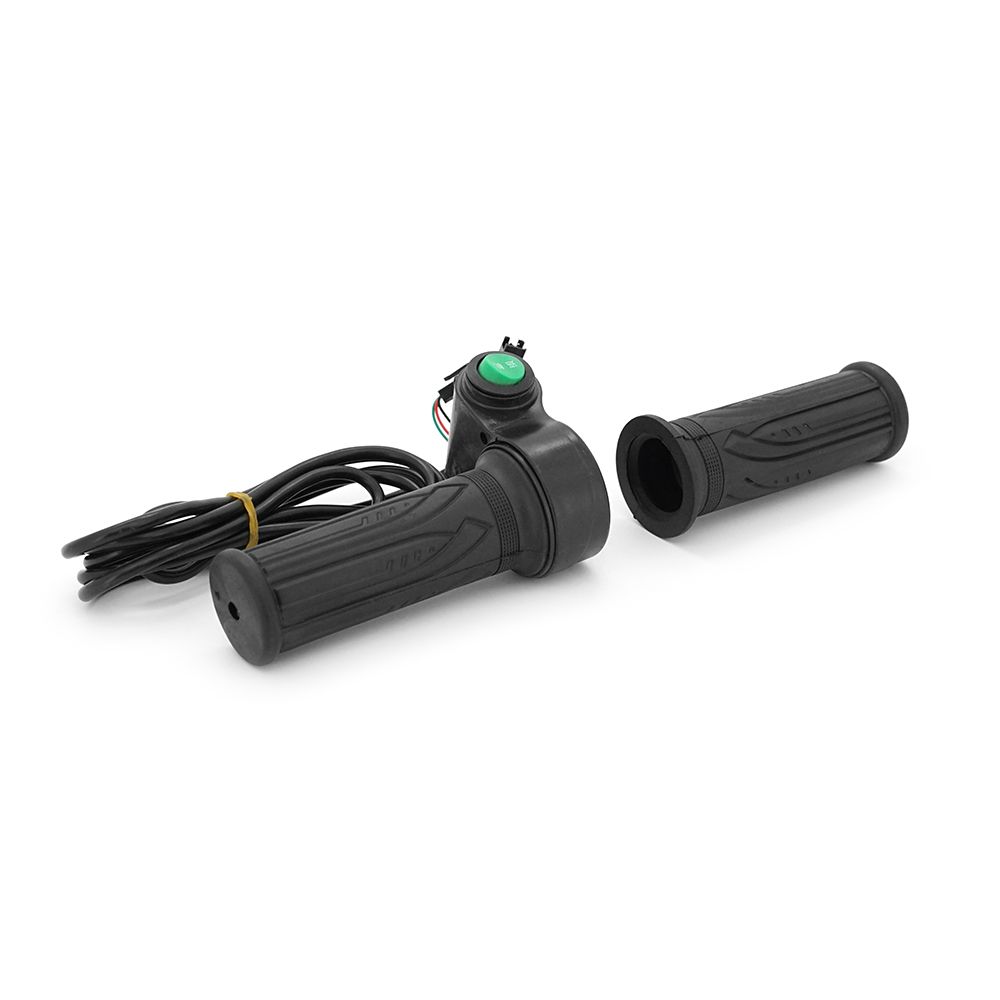
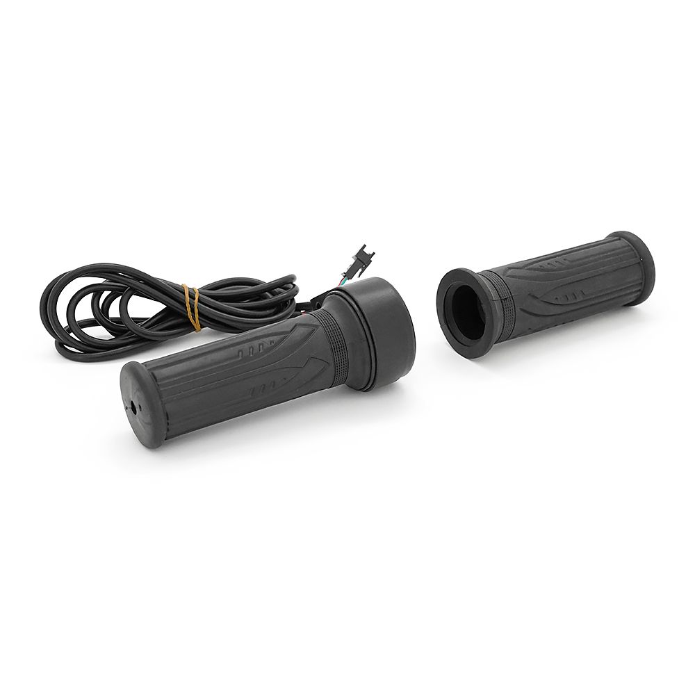
• A triplet of thin wires (usually black, red, and green) – for connecting the throttle grip.
Specifications:
• Housing size, mm: 228x82x42;
• Rated voltage, V: 48/60/64;
• Rated power, W: 1200;
• Current, A.: 42;
• Options: cruise control, three-speed switching, anti-theft protection function.
Dispatch to post branches, parcel lockers, or by courier to your doorstep. All packages are insured for 100% of value. Delivery time: 1–3 business days.
Flexible options: Cash on delivery at Nova Poshta branch or bank transfer invoice (IBAN) for individuals, FOP and companies.